This guide walks you through getting the SRD mini running: powering the unit, feeding it your antenna signal, distributing that signal to your receivers, and mounting it with the included steel wire clip. For an overview of the parts referenced here, see [SRD-Mini] Getting Started.
Connect to Power
The SRD mini can be powered three ways. Use whichever fits your rig.
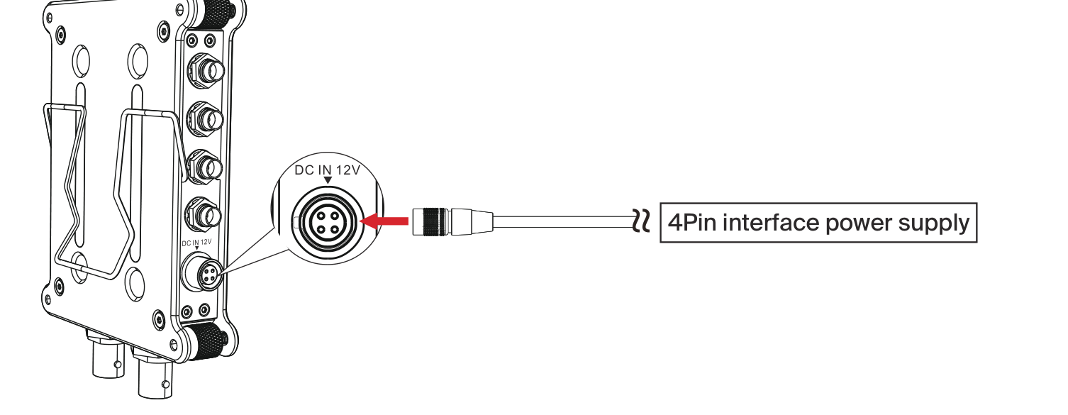
1. HRS 4-Pin DC (DC IN 12V)
The unit supports a 4-pin locking DC input. Connect the HRS interface cable from your power supply to the DC IN 12V port on the SRD mini to drive the RF splitter. This input accepts 12V to 16.8V DC.
2. USB-C
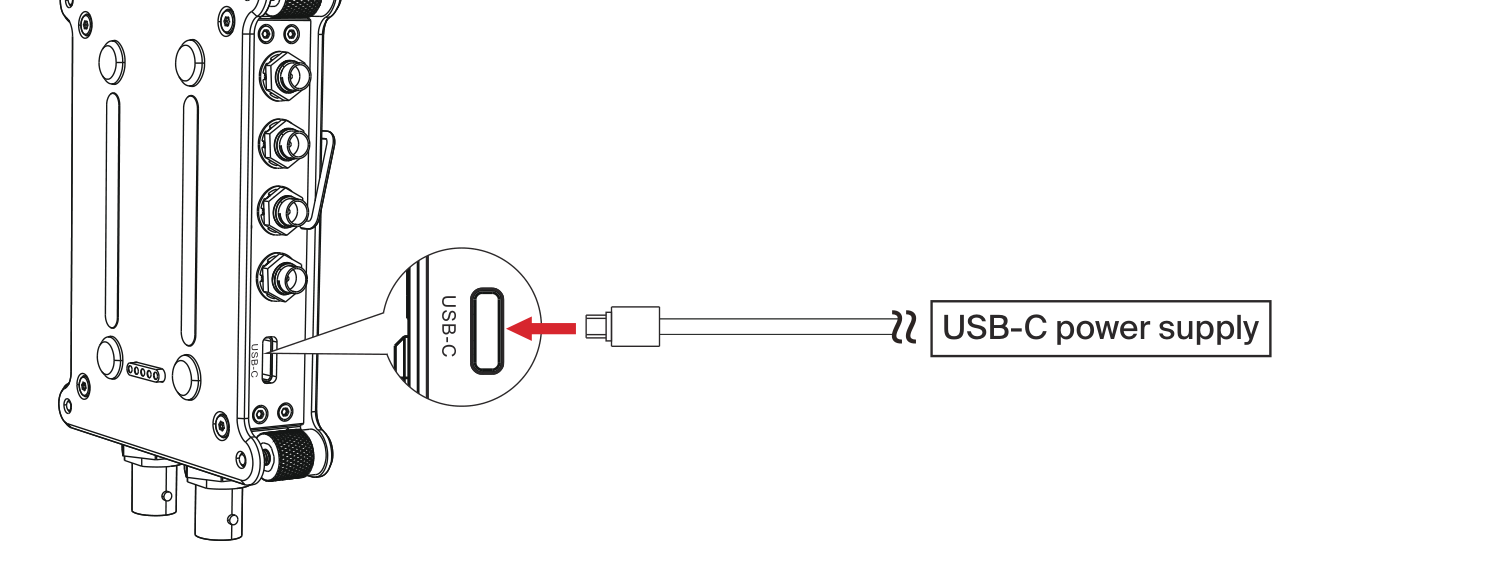
The unit also supports USB-C power. Insert a USB-C cable from your power source into the USB-C port on the side of the device and the RF splitter will operate normally. The USB-C input runs at 5V DC.
3. RPS (Stacked on an SPD Mini)
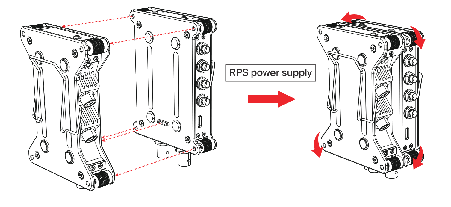
The unit supports the RPS power supply interface. Connect a Deity SPD mini power distributor to your power source, then stack the SRD mini onto it so the RPS pogo-pin contacts meet. Lock the four corner screws into the matching screw holes on the SPD mini to seat the two units together, and the RF splitter will draw power directly through the RPS interface.
RF Signal Distribution
Input
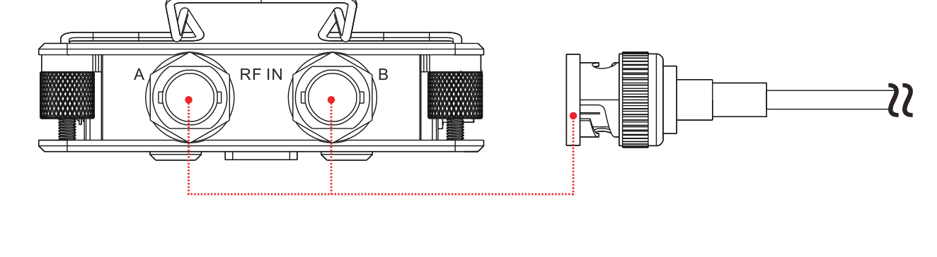
Feed your wireless RF signal into the SRD mini through the BNC RF input connectors on the bottom of the body. There are two inputs, labeled A and B (one per antenna).
Output
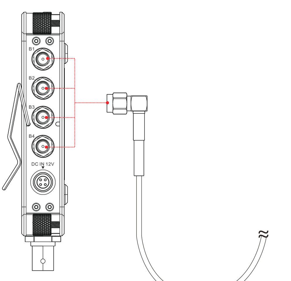
The RF output connectors (SMA) on the SRD mini connect to the RF receiving ports on your wireless devices using appropriate cables, distributing the split signal. The outputs on each side are labeled B1 through B4.
Installing the Steel Wire Clip
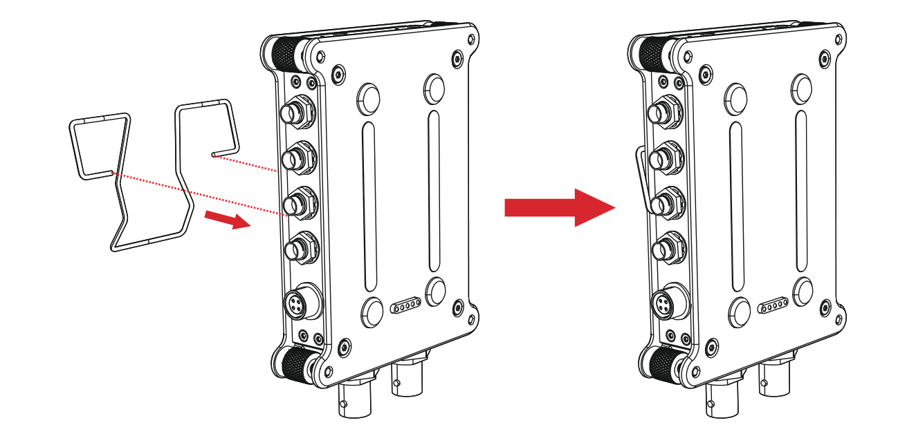
Install the included steel wire clip into the mounting holes on both sides of the body. Insert the fixing heads on each side into the holes to seat the clip. The clip gives you a quick, tool-free way to attach the unit to a bag or cart.
Cables You May Need
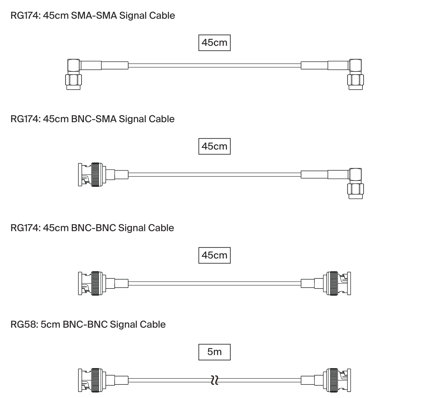
Depending on your antennas and receivers, you may need additional signal cables. The SRD mini uses BNC on its inputs and SMA on its outputs, so the following cables cover the common connections. These are sold separately.
| Cable | Type | Length |
|---|---|---|
| RG174 | SMA to SMA signal cable | 45cm |
| RG174 | BNC to SMA signal cable | 45cm |
| RG174 | BNC to BNC signal cable | 45cm |
| RG58 | BNC to BNC signal cable | 5m |