
This guide is a complete hardware reference for the SPD-1: every control, port, and indicator, the connector pinouts, the power input and output limits, and the compatible battery cups and adapter accessories. Read it before wiring the SPD-1 into your bag or cart.
Nomenclature
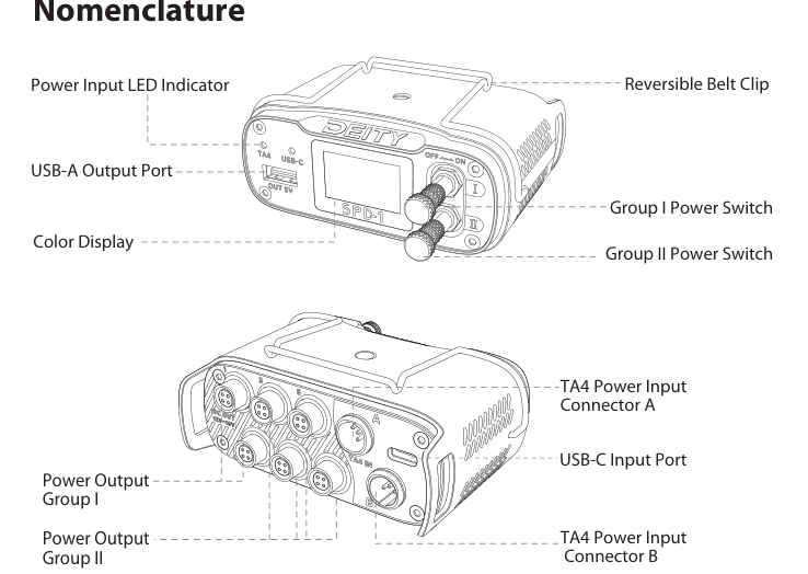
Front panel:
- Power Input LED Indicator
- USB-A Output Port
- Color Display (1.1 inch TFT)
- Reversible Belt Clip
- Group I Power Switch
- Group II Power Switch
Rear panel:
- TA4 Power Input Connector A
- TA4 Power Input Connector B
- USB-C Input Port
- Power Output Group I
- Power Output Group II
Connector Pinout
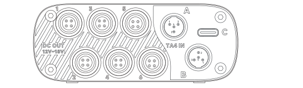
Power Output Connectors (Group I, Group II)
- DC-
- No Signal
- No Signal
- DC+
TA4 Power Input Connectors (A, B)
- DC-
- DAT
- CLK
- DC+
Note: The TA4 input wiring pinout is different than the Remote Audio and PSC NP-1 TA4 battery cup wiring. Do not use any of the Remote Audio or PSC TA4 battery cups with the SPD-1.
TA4 Power Inputs (A & B)
The two TA4 power inputs are compatible with any battery ranging from 12V to 18V. You can hot swap between the two TA4 inputs without interrupting power, so a fresh battery can take over on input B while input A is removed.
- When the power input is over 7V, the SPD-1 can turn on.
- When the power input falls below 6V, the SPD-1 turns off automatically.
- When the power input goes up to 24V, the SPD-1 turns off automatically.
TA4 LED Indicator
The LED next to each TA4 input reports the connected battery's voltage:
- Battery at 9V to 13V: the TA4 LED stays red.
- Battery at 13V to 18V: the TA4 LED stays green.
- Battery above 18V: the TA4 LED blinks red slowly.
- Battery below 9V: the TA4 LED stays off. It also stays red if connected to a non-smart battery.
- With a smart battery, the TA4 LED changes to red when the battery capacity falls below 10%.
USB-C Input Port
The USB-C port is a power input. Connect a 9V to 12V USB-C source to power the SPD-1, on its own or alongside a TA4 battery.
USB-C LED Indicator
- USB-C input at 9V to 12V: the USB-C LED stays green.
- USB-C input below 9V: the USB-C LED stays off.
Power Outputs (Group I & Group II)
The SPD-1 has 6 protected HRS outputs split into two switchable groups, plus one USB-A output.
- The SPD-1 features circuits with 7A over-current protection on each power output group (Group I and Group II).
- There are 2A polyswitch resettable fuses on each output of Group II. We suggest a maximum of 5A total for the power output on circuit Group II.
- We suggest a total of 10A max for the whole box and 5A max total for each output group.
- The SPD-1 will not output power when the input voltage rises above 18V.
- To isolate a power output group and help resolve ground loop issues, connect the Deity accessory SPD-HRISO (sold separately).
USB-A Output Port
The SPD-1 features a standard USB-A port that outputs a regulated 5V / 2A, useful for charging or powering low-draw USB accessories.
Compatible Battery Cups & Accessories
The following smart battery cups are compatible with the SPD-1:
- Audio Root eTA4f
- COGA Sound BPS TA4
- Deity SPD-T4BATT
- Remote Audio REM HIQCS1
- Sound Devices XL-SmartCup
A range of Deity adapter cables (sold separately) lets you power the SPD-1 from different sources:
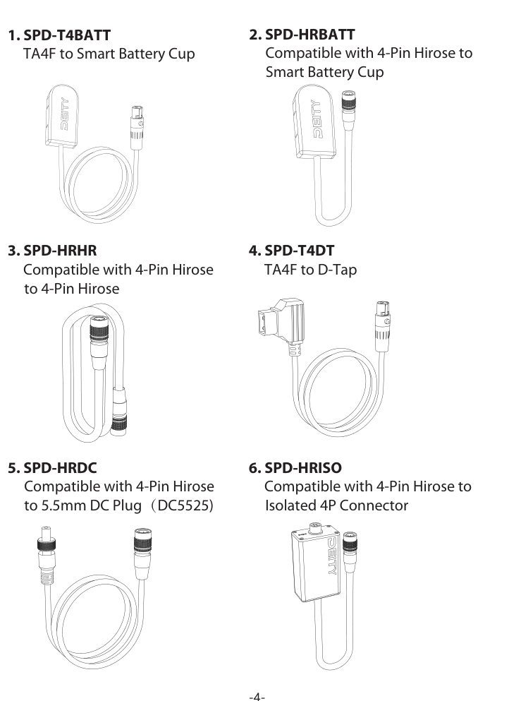
| Accessory | Connection |
|---|---|
| SPD-T4BATT | TA4F to Smart Battery Cup |
| SPD-HRBATT | 4-Pin Hirose to Smart Battery Cup |
| SPD-HRHR | 4-Pin Hirose to 4-Pin Hirose |
| SPD-T4DT | TA4F to D-Tap |
| SPD-HRDC | 4-Pin Hirose to 5.5mm DC Plug (DC5525) |
| SPD-HRISO | 4-Pin Hirose to Isolated 4P Connector |
| SPD-HR3U | 4-Pin Hirose to Triple USB-C |