
This guide identifies every port and control on the Deity SPD mini, shows how to fit the steel wire back clip, and walks through powering the unit from a TA4 source or a USB-C PD supply. It also explains what the power input indicator colors mean so you can read the unit's health at a glance.
Product Overview
The SPD mini carries its controls and outputs across the front face and the input edge. The front view shows the screen, power switch, and output ports:
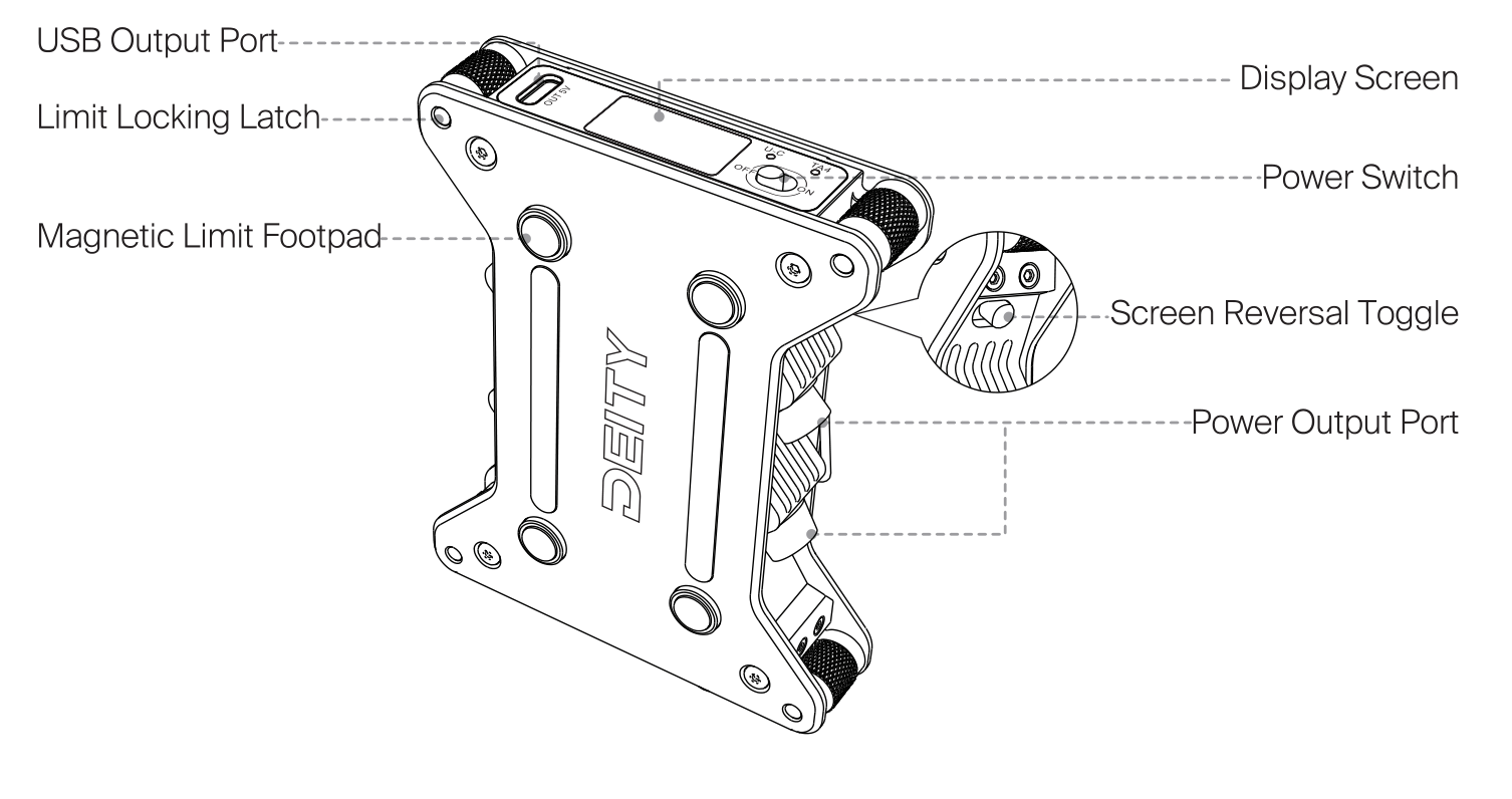
- Display Screen: the TFT screen that shows input voltage, battery percentage, runtime, and status.
- Power Switch: turns the unit on and off. When on, the screen lights up with power status information.
- Screen Reversal Toggle: flips the screen orientation so the display stays readable however the unit is mounted.
- USB Output Port: a USB output for powering or charging accessories.
- Power Output Port: the HRS4 output ports that feed power to your connected devices.
- Limit Locking Latch and Magnetic Limit Footpad: mounting features that let the unit seat and lock securely against a plate or cage.
The input edge carries the power connectors:
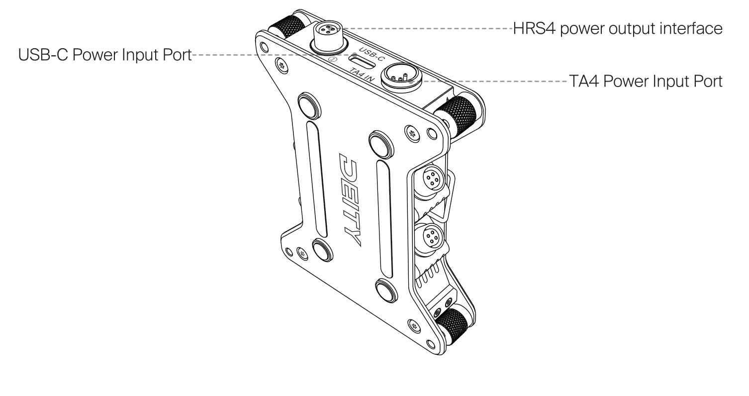
- TA4 Power Input Port: a 4-pin TA4 input for smart batteries and external power sources.
- USB-C Power Input Port: a USB-C input for PD power banks and adapters.
- HRS4 Power Output Interface: the 4-pin HRS4 outputs that distribute power to your gear.
Back Clip Installation
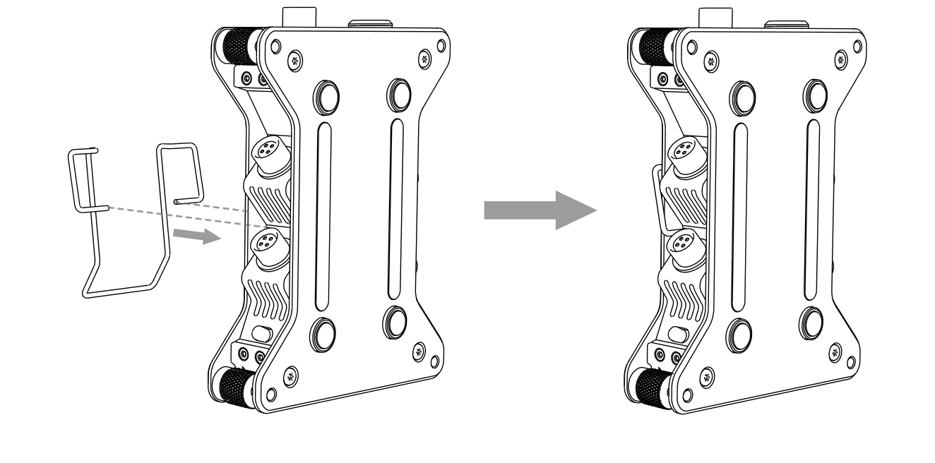
The SPD mini ships without the steel wire back clip attached. To fit it, align the clip with the channels on the back of the unit and slide it into place until it seats fully.
Powering the SPD mini
The SPD mini has two power input ports. Use whichever suits your power source. In both cases, once the source is connected, turn on the power switch and the screen lights up to display power status information.
1. TA4 Port
Connect an external power source or smart battery to the TA4 port. Turn on the power switch, and the screen lights up to display power status information.

2. USB-C Port
Connect the USB-C power cable from an external power source or smart battery to the USB-C power input port on the device. Turn on the power switch, and the screen lights up to display power status information.

Power Input Indicator
The input indicator changes color with the input voltage so you can confirm your source is in range before you rely on it.
TA4 Power Supply
| Indicator | Meaning |
|---|---|
| Red, steady on | Input below 13V |
| Green, steady on | Input above 13V |
| Red, flashing slowly | Input above 18V |
USB-C Power Supply (PD Protocol Adapter)
| Indicator | Meaning |
|---|---|
| Red, steady on | 9V or 12V |
| Green, steady on | 15V |
Note: When the input voltage reaches or exceeds 18V, the SPD mini treats it as an input overload and stops all output. See [SPD-Mini] Display Screen & Operation for the Overvoltage warning.