
The SF1 is an active directional antenna built to strengthen broadband UHF wireless signal reception. It covers a 470MHz to 960MHz frequency range and provides an active gain range of -9dB to +21dB, so it can compensate for the signal loss of long coaxial cable runs and also attenuate overly strong input signals to prevent receiver overload. With an IP54 weather rating, it is rugged enough for professional wireless audio work such as theatrical performances and film production. This guide covers what is in the box, the parts of the antenna, installation, gain setup, and placement.
What's in the Box
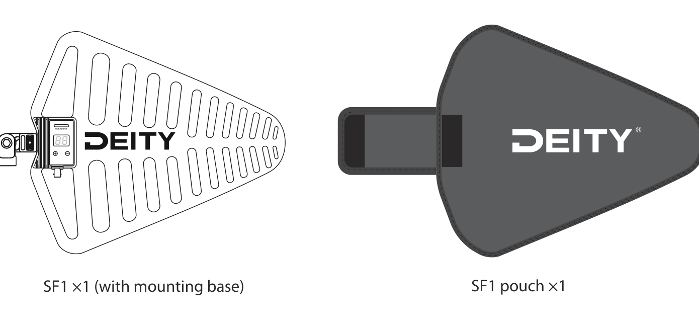
- SF1 antenna (1 pc, with mounting base)
- SF1 pouch (1 pc)
Get to Know Your SF1
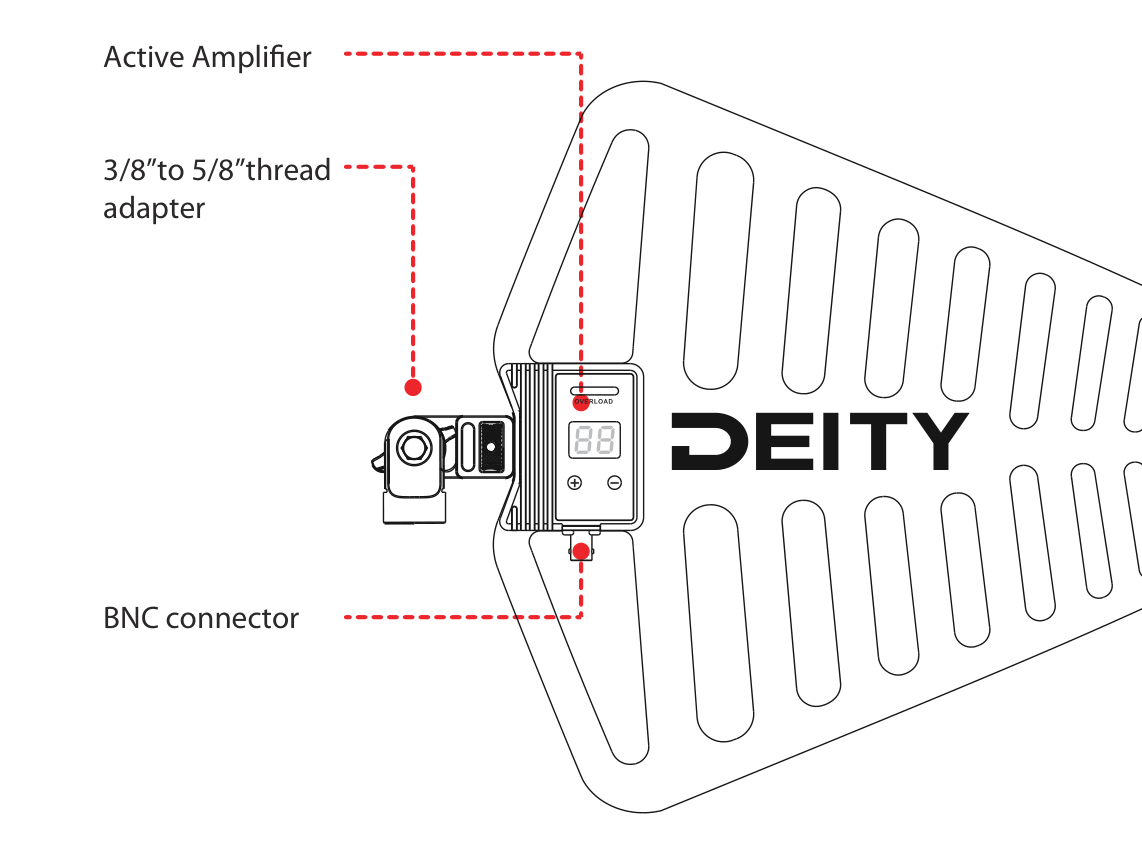
- Active Amplifier: the control module with the gain display and buttons. See Active Amplifier Configuration below.
- 3/8" to 5/8" thread adapter: lets the mounting base screw directly onto common 3/8" and 5/8" threaded stands.
- BNC connector: female BNC port that connects the antenna to your receiver or antenna distribution system.
Installation Guide
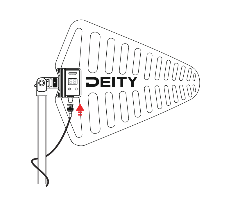
- Use the DEITY BNC antenna cable (or any 50-ohm low-loss coaxial cable) to connect the antenna to a receiver or antenna distribution system.
- This antenna must be used only with receivers or distribution systems that supply a 12 to 16.8 V DC bias.
- The SF1 comes with a mounting base and can be screwed directly onto 3/8" and 5/8" threaded mounts. For other thread sizes, use an appropriate adapter.
- Aim the antenna toward the desired coverage area.
For shorter cables, reduce the gain setting; for longer cables, increase the gain accordingly. Signal loss depends not only on cable length but also on cable quality: a poorly made 15-meter cable may need more gain than a 30-meter high-quality low-loss cable. Refer to the cable attenuation table in [SF1] Specifications for recommended gain settings, or consult the cable manufacturer to determine signal loss before setting gain.
Active Amplifier Configuration
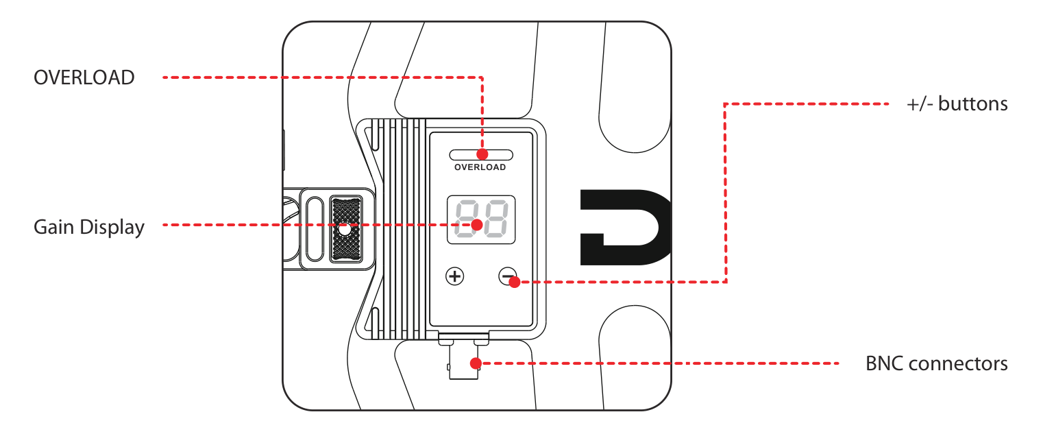
- OVERLOAD: when the signal is overloaded, this indicator lights up red. Reduce the gain if it does.
- Gain Display: a digital display that shows the currently set gain value.
- + / - Buttons: gain adjustment buttons in 1dB increments, adjustable from -9dB to +21dB.
- BNC Connector: female BNC port. When connected to a receiver or distribution system that supplies a 12 to 16.8V DC bias, the antenna operates in active mode. When connected to a system without DC power, it functions as a passive antenna, providing 6dB of gain from the antenna panel in passive mode.
Note: The gain setting of the active amplifier is intended solely to compensate for the calculated signal loss in the cable. Additional signal gain does not imply better RF performance. Excessive gain may amplify all signals within the RF range, including interference and ambient RF noise.
Antenna Placement Recommendations
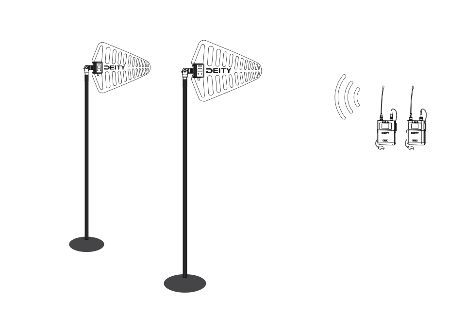
- The antenna and receiver must operate within the same frequency band (470MHz to 960MHz).
- Install antennas at least one wavelength apart (a minimum distance of 1 meter is recommended).
- Position antennas so there is a clear line of sight to the transmitters, including into the audience.
- Mount antennas at a height and keep them away from metal objects.
Important: Before using the wireless system during a speech or performance, always perform a "walk-around" test to verify coverage. Experiment with antenna placement to find the optimal position. If necessary, mark any low-signal areas and instruct the presenter or performer to avoid these zones.