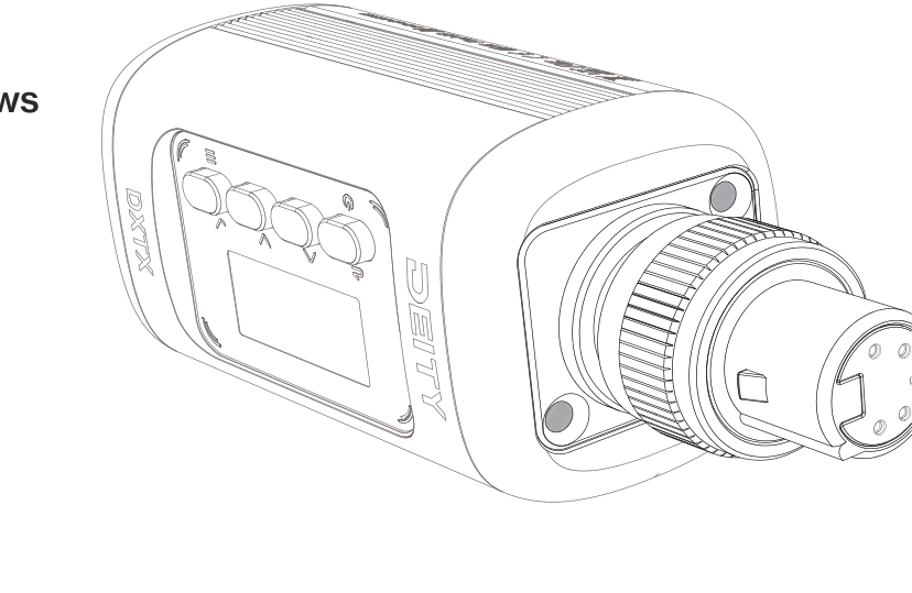
This guide covers the physical setup of your DXTX plug-on transmitter: the four control buttons, fitting the antenna and microphone, inserting the microSD card and batteries, powering and transferring files over USB-C, reading the LED indicators, and swapping the XLR connector between 3-pin and 5-pin.
Button Functions
The DXTX is driven by four buttons beside the display. Many buttons have a short-press and a long-press action.
| Power / Back Button | Long press to turn the DXTX on or off. A short press returns to the previous screen. On the main screen, a short press mutes the audio, and a quick triple tap locks the screen. |
| Up / Down Buttons | Select options and adjust values in the setup screens. Long press Up to open the recording interface. Long press Down to open the timecode interface. |
| OK / Menu Button | Opens the menu and confirms the highlighted item. When using the 5-pin stereo input, press and hold this button to quickly switch which channel's gain you are adjusting. |
Note: The long-press shortcuts for recording, timecode, and mute can be turned on or off under SYSTEM > HOTKEY. See [DXTX] Menu Reference.
Antenna Installation
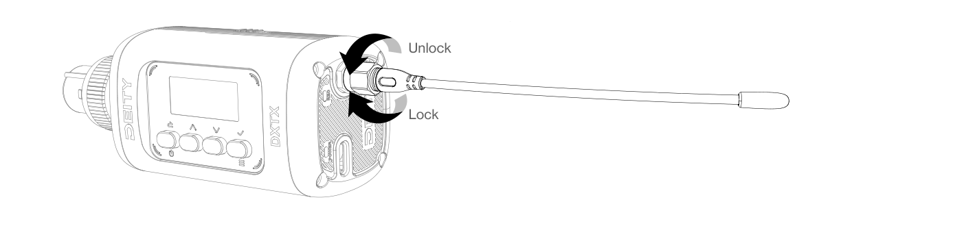
The DXTX uses a whip antenna with an SMA interface. Rotate and thread the matching antenna onto the antenna socket on the bottom of the DXTX, then tighten it to lock it in place.
Microphone Installation
Insert your shotgun or handheld microphone into the XLR connector on the top of the DXTX, then rotate it to lock the microphone in place.
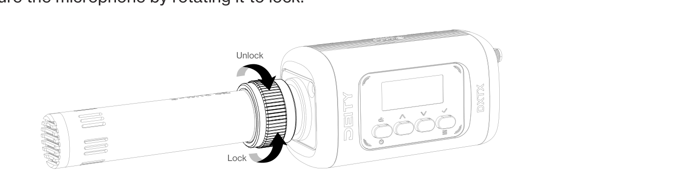
After the mic is fitted, set the correct mic power (LINE, MIC 5V, or MIC 48V for phantom-powered mics) under TX MODE.
Insert the microSD Card
The microSD card slot sits at the lower part of the battery compartment. Open the battery compartment cover and insert the microSD card into the slot before you install the AA batteries.
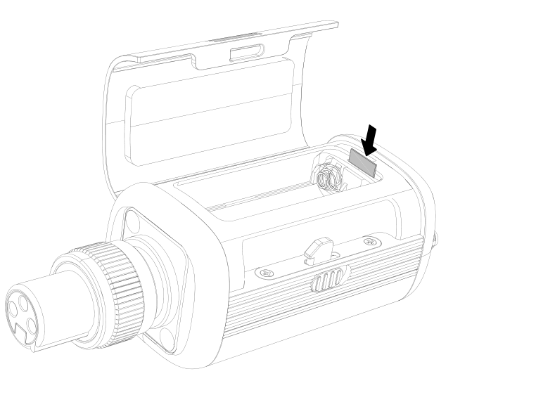
For best recording stability, format a new card in the device under SYSTEM > SD CARD > FORMAT.
Battery Installation
Flick the unlock knob on the battery compartment cover on the side of the device, open the cover, and install the two AA batteries with the correct polarity.
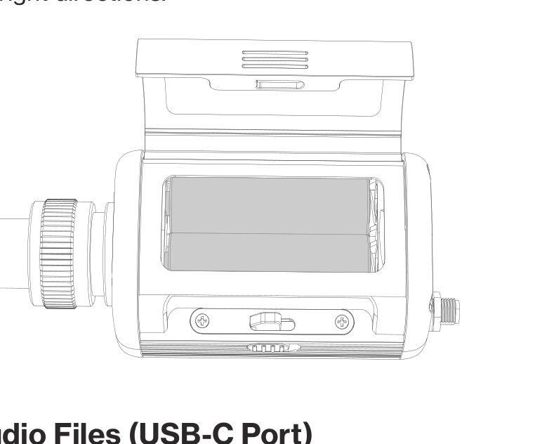
Note: The included DEITY AA batteries are disposable lithium (non-rechargeable) cells. Do not attempt to charge them. Set your battery type under BATTERY so the DXTX estimates remaining life accurately.
Power and File Transfer over USB-C
You can power the DXTX from a USB-C cable connected to a DC adapter. The USB-C port also handles two data tasks:
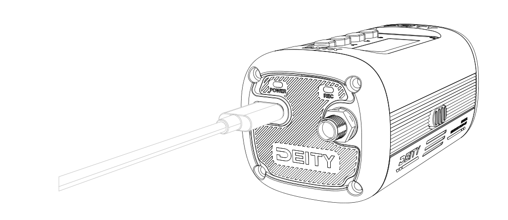
- Read files: To copy recordings off the microSD card, open SYSTEM > READER, then connect the DXTX to a computer with USB-C.
- Real-time audio: The USB-C port can also output audio, so the DXTX can send sound directly to a computer or other device in real time.
LED Indicators
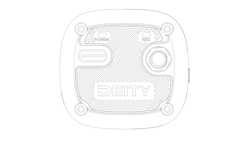
| REC LED | Stays red while the device is recording. |
| POWER LED | Glows green when the battery is good, turns red when the battery is low, and slow-flashes red when the device is muted. |
You can turn the LED indicators on or off under the LED menu.
Replacing the XLR Connector (3-Pin or 5-Pin)
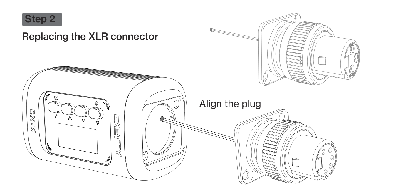
The DXTX can swap its XLR 3-pin connector for a 5-pin connector, which lets you carry two microphone inputs (MIC1 and MIC2) for stereo or dual-mic work. After swapping to a 5-pin connector, the on-screen interface changes slightly, but the functions stay largely the same. The interfaces described in the other guides are based on the 3-pin connector.
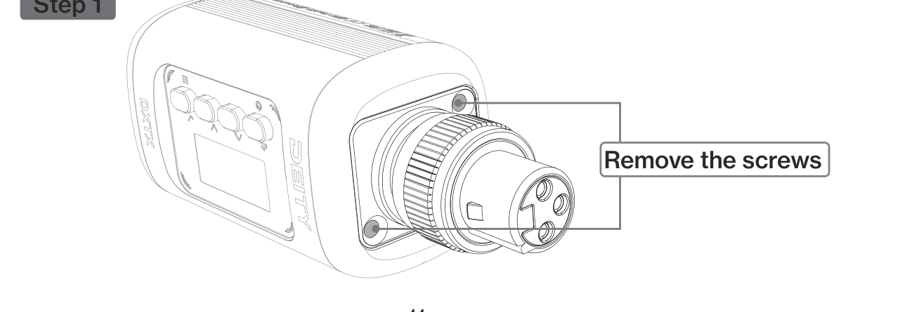
Step 1: Remove the screws
Remove the screws on the top of the product, then take out the 3-pin connector.
Step 2: Fit the new connector
Align the plug of the new connector with the internal socket of the product and seat it fully.
The pin assignments for each connector are shown below.
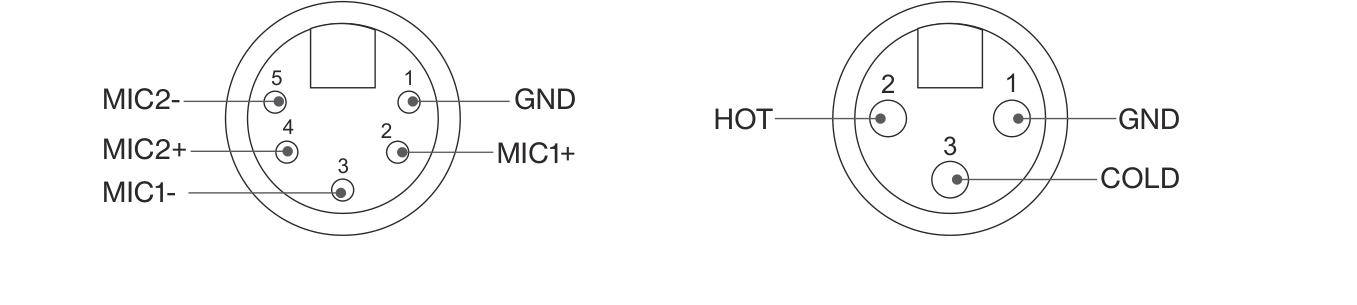
- 5-pin: 1 = GND, 2 = MIC1+, 3 = MIC1-, 4 = MIC2+, 5 = MIC2-
- 3-pin: 1 = GND, 2 = HOT, 3 = COLD
Step 3: Lock the screws
Secure the panel by tightening the screws.